inkpictureでstrokeを追加したいです。 への返答

投稿で使用できる特殊コードの説明。(別タブで開きます。)
以下の返答は逆順(新しい順)に並んでいます。
投稿者 snowmansnow (社会人)
投稿日時
2020/4/4 00:58:03
遅くなりました。
Set Strokes(0) = .CreateStroke(MakePoints(7000, 4000, 6897, 4776, 6598, 5500, 6121, 6121, 5500, 6598, 4776, 6897, 4000, 7000), Null)
Set Strokes(1) = .CreateStroke(MakePoints(4000, 7000, 3223, 6897, 2500, 6598, 1878, 6121, 1401, 5500, 1102, 4776, 1000, 4000), Null)
Set Strokes(2) = .CreateStroke(MakePoints(1000, 4000, 1102, 3223, 1401, 2500, 1878, 1878, 2500, 1401, 3223, 1102, 3999, 1000), Null)
Set Strokes(3) = .CreateStroke(MakePoints(3999, 1000, 4776, 1102, 5500, 1401, 6121, 1878, 6598, 2500, 6897, 3223, 7000, 3999), Null)
くらいだと、円に近くなりますが、始点と終点はカーブが効かないのはなんとかならないのでしょうか?
助けて下さい~。
'https://teratail.com/questions/111853さんを参考にして貼り付けた画像の一方は、何かカーブがきついですが、
これは何か違う仕様なのでしょうか?
AddStrokesAtRectangleで四角を指定すると、丸くなるのでしょうか?
明日以降できたらやってみようと思っていますが、出来ないかもしれません・・・
とっかりぼうやは、私の言語に問題があるようでした。方言かなぁと思って家族に聞いてみたら、
使わないようでした。とんがぼうしが正解?かもしれません。ごめんなさい。
投稿者 snowmansnow (社会人)
投稿日時
2020/4/3 20:37:55
大変ありがとうございます。
早速試してみました。
GetpointsでもGetFlattenedBezierPointsでもデータを取得でき、
後者の方がデータが少ない(曲線だから?)のを
再度両方描画してみました。(3ストロークまで、geenpointsとかみたいに)
前者は、ほぼ元データと見かけが同一で、後者は縦が少し短くなって上に移動してるようでした。
GetFlattenedBezierPointsのデータは、どういう構成になっているのでしょうか?
何か記載してるものございますか?
'https://docs.microsoft.com/en-us/windows/win32/api/msinkaut/nf-msinkaut-iinkstrokedisp-getflattenedbezierpointsに
The Variant result contains an array in the form x1, y1, x2, y2, ”and so on, of the Bezier points.”
と書いてありますが?後半がわかりませんでした。
とても勉強になります。
よろしくお願いします。
投稿者 魔界の仮面弁士 (社会人)
投稿日時
2020/4/3 18:19:19
ストロークを四分割すれば円を描けるかと思ったのですが、
FitToCurve で制御するのは難しそう。
円周上にプロットしていくしかないのかな…。
FitToCurve で制御するのは難しそう。
円周上にプロットしていくしかないのかな…。
Private Sub CommandButton1_Click()

    'チェックボックスが off なら正方形、on なら円になるかと思ったけれど…。

    Dim IsCircle As Boolean

    IsCircle = CheckBox1.Value


    InkPicture1.Ink.DeleteStrokes


    '0: 右上部┓

    '1: 右下部┛

    '2: 左下部┗

    '3: 左上部┏

    Dim Strokes(3) As IInkStrokeDisp

    With InkPicture1.Ink

        Set Strokes(0) = .CreateStroke(MakePoints(4400, 0, 8800, 0, 8800, 4400), Null)

        Set Strokes(1) = .CreateStroke(MakePoints(8800, 4400, 8800, 8800, 4400, 8800), Null)

        Set Strokes(2) = .CreateStroke(MakePoints(4400, 8800, 0, 8800, 0, 4400), Null)

        Set Strokes(3) = .CreateStroke(MakePoints(0, 4400, 0, 0, 4400, 0), Null)

    End With


    Dim n As Integer

    For n = 0 To 3

        With Strokes(n).DrawingAttributes

            .FitToCurve = IsCircle

            .Color = QBColor(n + 9)

        End With

    Next


    InkPicture1.AutoRedraw = False

    With InkPicture1.Ink.CreateStrokes()

        For n = 0 To 3

            .Add Strokes(n)

        Next

    End With

    InkPicture1.AutoRedraw = True

End Sub
投稿者 魔界の仮面弁士 (社会人)
投稿日時
2020/4/3 16:41:06
> 〇は〇で表示されずに栗みたいなとっかりぼうやみたいになりました。
「とっかりぼうや」が何のことか、検索してもわからなかったのですが、
とにかく、円をうまく描けなかったということで理解しました。
座標点をより細かくプロットしてみては如何でしょうか。
元々、フリーハンドで描かれる前提なので、
ペンやスタイラス(あるいは指やマウス)をよほど高速に動かさない限り、
一つ一つの座標は、近しい位置にプロットされると思います。
> besier曲線とかいうものでしょうか?
下記のページで、イメージが掴めるかも知れません。
https://mizucoffee.github.io/nth-order-bezier-curves-canvas/index.html
https://nixeneko.hatenablog.com/entry/2015/06/26/075022
> 手で入力したストロークをデータに取り出せたら、理解ができるかもしれませんが、
> やりかたがわかりません。御教授願えますでしょうか?
ジェスチャーのストロークなら、Gesture イベントの Strokes 引数を使います。
インクからなら、InkPicture1.Ink.Strokes です。
これらを For Each で列挙すれば、個々のストロークが得られますので、
そのストロークが保持している座標群を、GetPoints メソッドで取り出します。
(GetFlattenedBezierPoints なんてのもあります。
Option Explicit

Option Base 0

Private Sub CommandButton1_Click()

    'ジェスチャーモードの場合、インクが時間経過で消えてしまい、

    '解析中に元のインクが Deleted になることがあります。

    'それを避けるため、列挙前にあらかじめ元のインクを複製しておきます。

    Dim Ink As InkDisp

    Set Ink = InkPicture1.Ink.Clone()


    'インクデータ内のストロークを解析して Sheet1 に表示します。

    Sheet1.Cells.Clear

    Dim st As IInkStrokeDisp

    Dim points() As Long, matrix() As Long

    Dim x As Integer, y As Integer

    x = 1

    For Each st In Ink.Strokes

        'GetPoints メソッドは、プロットされた座標群のうち、

        'Index 番目か始まる Count 組までの座標を

        'X1,Y1,X2,Y2,…形式な Long 型の一次元配列で返します。

        '

        '引数 Count:=3 を指定すれば 3 組となり、

        'points(0)~points(5) の 6 つの値が返されます。

        '

        '引数を省略した場合(Index:=ISC_FirstElement, Count:=AllElements)は、

        '全ての座標が返されます。

        '

        points = st.GetPoints()


        '確認のため、取得した座標を Sheet1 に表示させてみます。

        matrix = GetMatrixFromPoints(points)

        y = UBound(matrix, 1) + 1

        Sheet1.Cells(1, x + 0).Value = "#" & CStr(st.id) & "のX値"

        Sheet1.Cells(1, x + 1).Value = "#" & CStr(st.id) & "のY値"

        Sheet1.Range(Sheet1.Cells(2, x + 0), Sheet1.Cells(y + 1, x + 1)).Value = matrix

        x = x + 3

    Next

End Sub


'X, Y 座標が順に並んだ一次元配列を、2 次元配列に変換します

Private Function GetMatrixFromPoints(ByRef p() As Long) As Long()

    Dim matrix() As Long

    Dim l As Long, u As Long

    u = UBound(p, 1)

    ReDim matrix(u \ 2, 2) As Long

    For l = 0 To u Step 2

        matrix(l \ 2, 0) = p(l + 0)

        matrix(l \ 2, 1) = p(l + 1)

    Next

    GetMatrixFromPoints = matrix

End Function
投稿者 snowmansnow (社会人)
投稿日時
2020/4/3 13:08:52
夜分、早朝にありがとうございます。遅くなりましてごめんなさい。
'https://teratail.com/questions/111853さんを参考に画像を取れましたが、
ここに画像が貼れなかったので、言葉にします。
'http://www.vbforums.com/showthread.php?763319-Drawing-shapes-on-ink-pictureさんを参考に
inkpikture1に〇、inkpikture2に□、inkpikture3に△を表示させてみました。
〇は〇で表示されずに栗みたいなとっかりぼうやみたいになりました。
その後で、inkpikture1にコピペして、3ストローク書き込めるのか実験してみました。
でも〇?△?も変な形になったので、(これが「描画結果はこうなりますね」の画像です)
FitToCurveを教えていただいたので、直線、曲線の設定はこれじゃないかと思いましたが、
FitToCurveがtrueの時のデータ仕様がわかりません。
besier曲線とかいうものでしょうか?二次?三次?
x1、y1、x2、y2、p1x、p1y、p2x、p2y~pxx、pxyでしょうか?
それともpは固定個数ですか?
手で入力したストロークをデータに取り出せたら、理解ができるかもしれませんが、
やりかたがわかりません。御教授願えますでしょうか?
分からない事だらけで、
Private Sub CommandButton24_Click()
InkPicture1.AutoRedraw = False
InkPicture1.Ink.DeleteStrokes '←クリア処理(元コードには無かったもの) InkPicture1.Ink.CreateStrokes().Add InkPicture1.Ink.CreateStroke(greenPoints, Null)
Dim myStroke As Object
For Each myStroke In InkPicture1.Ink.Strokes
myStroke.DrawingAttributes.Color = RGB(0, 255, 0)
Next
stc = InkPicture1.Ink.Strokes.Count
InkPicture1.Ink.CreateStrokes().Add InkPicture1.Ink.CreateStroke(bluePoints, Null)
Dim myStroke2 As Object
Dim st As Long
For Each myStroke2 In InkPicture1.Ink.Strokes
If st >= stc Then
myStroke2.DrawingAttributes.Color = RGB(0, 0, 255)
Else
st = st + 1
End If
Next
stc = InkPicture1.Ink.Strokes.Count
With InkPicture1.Ink.CreateStrokes()
.Add InkPicture1.Ink.CreateStroke(brownPoints, Null)
Dim DrawingAttributes As InkDrawingAttributes
Set DrawingAttributes = InkPicture1.DefaultDrawingAttributes.Clone()
DrawingAttributes.FitToCurve = True
.ModifyDrawingAttributes DrawingAttributes
End With
Dim myStroke3 As Object
Dim st2 As Long
For Each myStroke3 In InkPicture1.Ink.Strokes
If st2 >= stc Then
myStroke3.DrawingAttributes.Color = RGB(255, 0, 0)
Else
st2 = st2 + 1
End If
Next
InkPicture1.AutoRedraw = True
End Sub
'https://detail.chiebukuro.yahoo.co.jp/qa/question_detail/q1238549967さんを参考に
筆順を色付けしてみました。
withでやってみたかったのですが、できませんでした。
何かやり方が、ございますでしょうか?
お手数かけますが、よろしくお願いします
投稿者 魔界の仮面弁士 (社会人)
投稿日時
2020/4/3 09:09:16
あれ。※2系統と※3系統とで、青と茶の着色が逆になっちゃってますね…。
適宜読み替えてください。
適宜読み替えてください。
投稿者 魔界の仮面弁士 (社会人)
投稿日時
2020/4/3 01:38:07
> ※1から※3の、それぞれ単独で描く時とも形が違うようで、
具体的にはどのように違うのでしょうか?
そもそもどういう図形を描画したいのかが分からないので、
比較画像を貼っていただいた方が良さそうです。
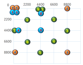
とりあえず、ストロークとしてプロットされたのは、下記の座標ですね。
💚※1系統が緑
🤎※2系統が茶
💙※3系統が青

提示頂いたコードですと、Bézier 曲線が有効になっているのは、
結局 ※3 だけのようですが…それは意図的にそうしているのでしょうか?
元のコードは With 句の使い方が不自然で読み辛かったので、少し整理して書き直してみました。
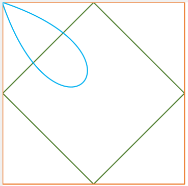
描画結果はこうなりますね。
(この画像はストロークを識別できるよう、DrawingAttributes.Color も設定したものです)

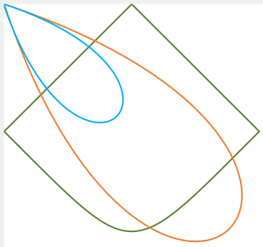
FitToCurve = True を、※1、※2、※3 すべてに指定するとこんな感じ。

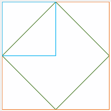
FitToCurve = True をいずれにも指定しないとこうなります。

具体的にはどのように違うのでしょうか?
そもそもどういう図形を描画したいのかが分からないので、
比較画像を貼っていただいた方が良さそうです。
とりあえず、ストロークとしてプロットされたのは、下記の座標ですね。
💚※1系統が緑
🤎※2系統が茶
💙※3系統が青

提示頂いたコードですと、Bézier 曲線が有効になっているのは、
結局 ※3 だけのようですが…それは意図的にそうしているのでしょうか?
元のコードは With 句の使い方が不自然で読み辛かったので、少し整理して書き直してみました。
Option Explicit


Private greenPoints() As Long

Private bluePoints() As Long

Private brownPoints() As Long


Private Sub CommandButton1_Click()

    InkPicture1.AutoRedraw = False

    InkPicture1.Ink.DeleteStrokes   '←クリア処理(元コードには無かったもの)

    InkPicture1.Ink.CreateStrokes().Add InkPicture1.Ink.CreateStroke(greenPoints, Null)

    InkPicture1.Ink.CreateStrokes().Add InkPicture1.Ink.CreateStroke(bluePoints, Null)

    With InkPicture1.Ink.CreateStrokes()

        .Add InkPicture1.Ink.CreateStroke(brownPoints, Null)

        Dim DrawingAttributes As InkDrawingAttributes

        Set DrawingAttributes = InkPicture1.DefaultDrawingAttributes.Clone()

        DrawingAttributes.FitToCurve = True

        .ModifyDrawingAttributes DrawingAttributes

    End With

    InkPicture1.AutoRedraw = True

End Sub


Private Sub UserForm_Initialize()

    greenPoints = MakePoints(4400, 0, _

                             6600, 2200, _

                             8800, 4400, _

                             6600, 6600, _

                             4400, 8800, _

                             2200, 6600, _

                             0, 4400, _

                             2200, 2200, _

                             4400, 0)


    bluePoints = MakePoints(0, 0, _

                            8800, 0, _

                            8800, 8800, _

                            0, 8800, _

                            0, 0)


    brownPoints = MakePoints(0, 0, _

                             4400, 0, _

                             4400, 4400, _

                             0, 4400, _

                             0, 0)

End Sub
描画結果はこうなりますね。
(この画像はストロークを識別できるよう、DrawingAttributes.Color も設定したものです)

FitToCurve = True を、※1、※2、※3 すべてに指定するとこんな感じ。

FitToCurve = True をいずれにも指定しないとこうなります。

投稿者 (削除されました) ()
投稿日時
2020/4/3 00:40:59
(削除されました)
投稿者 snowmansnow (社会人)
投稿日時
2020/4/2 21:05:39
お世話になります。
inkpictureでstrokeをプログラムで追加したいです。
Private Sub CommandButton19_Click()
'http://www.vbforums.com/showthread.php?763319-Drawing-shapes-on-ink-picture
'★↑参考にしました
'@@This needs work:
'
' As it is, it seems to only draw 4 of the vertices, not all 8.
' Because of this "FitToCurve" produces a mess instead of anything
' resembling a circle.
Dim DrawingAttributes As MSINKAUTLib.InkDrawingAttributes
Dim Strokes As MSINKAUTLib.InkStrokes
With InkPicture1
Set DrawingAttributes = .DefaultDrawingAttributes.Clone
With DrawingAttributes
.FitToCurve = True
End With
.AutoRedraw = False
With .Ink ※1
Set Strokes = .CreateStrokes()
Strokes.Add .CreateStroke(MakePoints(4400, 0, _
6600, 2200, _
8800, 4400, _
6600, 6600, _
4400, 8800, _
2200, 6600, _
0, 4400, _
2200, 2200, _
4400, 0), _
Null)
End With
With .Ink ※2
Set Strokes = .CreateStrokes()
Strokes.Add .CreateStroke(MakePoints(0, 0, _
8800, 0, _
8800, 8800, _
0, 8800, _
0, 0), _
Null)
End With
With .Ink ※3
Set Strokes = .CreateStrokes()
Strokes.Add .CreateStroke(MakePoints(0, 0, _
4400, 0, _
4400, 4400, _
0, 4400, _
0, 0), _
Null)
End With
Strokes.ModifyDrawingAttributes DrawingAttributes
.AutoRedraw = True
End With
'Flip to Select:
'@@Ideally we'd select the new Strokes as well but I haven't figured out how yet.
'optMode(omSelect).Value = True
End Sub
Private Function MakePoints(ParamArray CoordList() As Variant) As Long()
'http://www.vbforums.com/showthread.php?763319-Drawing-shapes-on-ink-picture
Dim Coords() As Long
Dim I As Long
ReDim Coords(UBound(CoordList))
For I = 0 To UBound(CoordList)
Coords(I) = CoordList(I)
Next
MakePoints = Coords
End Function
で、なんとなく追加できるのですが、
※1から※3の、それぞれ単独で描く時とも形が違うようで、
直線以外は、どうデータ表現して、どう書込みデータにするか、わからないです。
お手数かけますが、よろしくお願いします。
gestureもstrokeも教えていただきましたので、基本の一部は勉強できたつもりです。
inkpicture漬けから少し離れて、またしばらくたってから、
違う目線で、またinkpictureの基本の他の部分にも携わってみたいと思います。
また、その時にお聞きしたい事が出来ましたら宜しくお願い致します。
お2人とも、貴重なお時間いただきましてありがとうございます。
なお、AddStrokesAtRectangleは、stroke選択の時の可動?な四角の事かなぁと思いましたが、
四角の枠線みたいでしたので、また今度やってみようと思います。お騒がせしました。